Survey Data for Site Plan Rendering
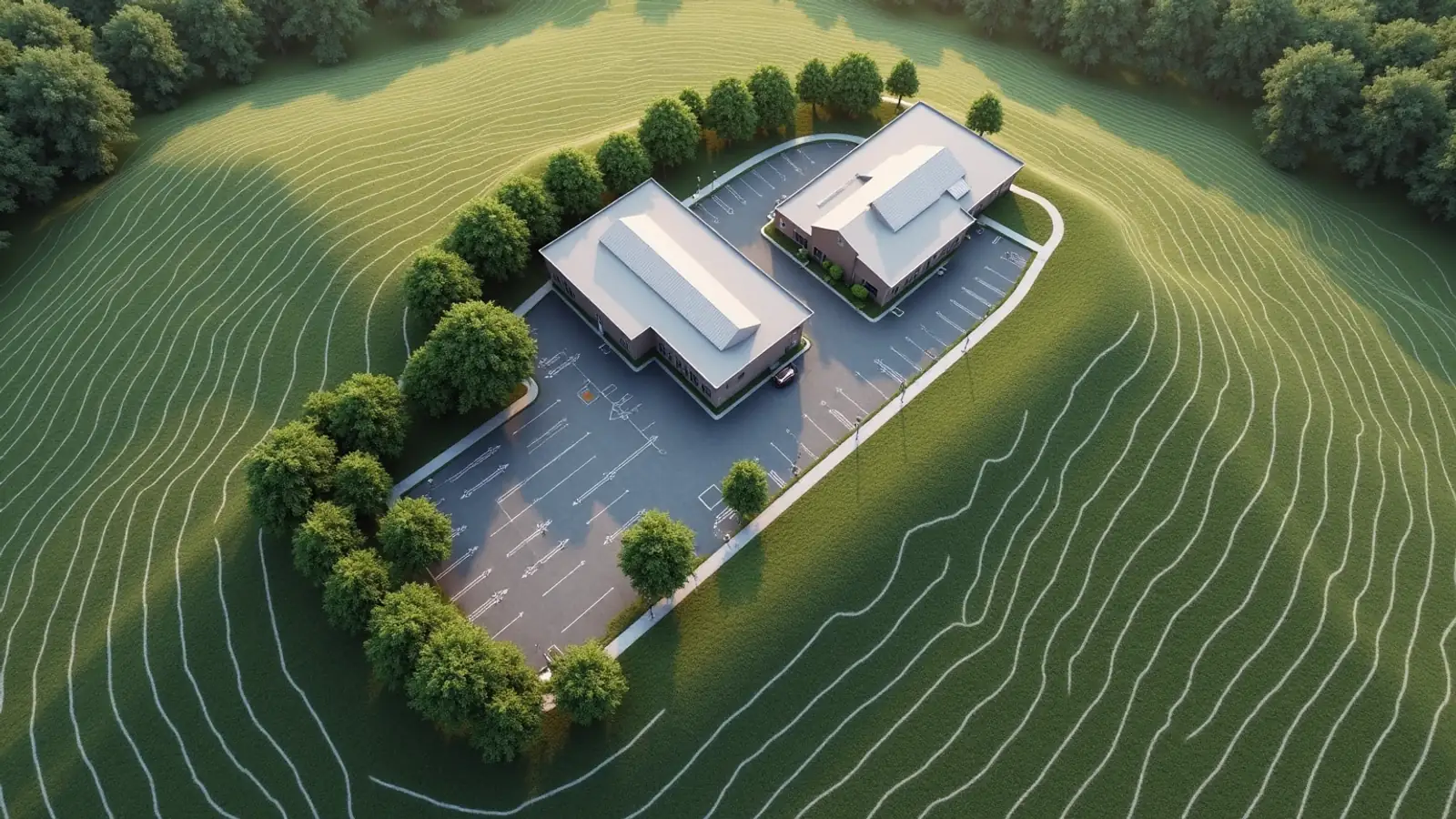
A site plan rendering needs four things: the boundary survey with property lines and setbacks, topographic contours or spot elevations, existing conditions including trees, utilities, drives and any structures to remain, and the surrounding context including adjacent buildings and the street. Boundary and topography are the blocking pair. Without contours the site is drawn flat, and a flat drawing of a sloped site will misrepresent grade, retaining, accessibility and how the building meets the ground.
Of every input we ask for, survey data is the one most often assumed to be unnecessary and most often responsible for a rendering having to be redone. This is the checklist behind our site plan rendering work.
The four inputs
Boundary survey. Property lines, bearings and distances, easements and setbacks. This establishes what can be shown inside the parcel and is the reference any reviewer will check the image against. Easements in particular constrain where buildings, parking and planting can go.
Topography. Contours, ideally as CAD or a point file rather than a scanned PDF. This is what lets the ground be modeled as it is. It determines retaining walls, steps, ramps, accessible routes, drainage direction and how the building sits rather than floats.
Existing conditions. Trees with size and species where they are to remain, existing structures, drives, utilities, poles and overhead lines. Trees to be preserved are frequently a condition of approval, so their real position and canopy matter.
Context. Adjacent buildings with approximate heights, the street cross section, and photographs from the actual approach directions. Photographs are cheap, take minutes, and are the item most often skipped.
What formats are useful
CAD in the project coordinate system is best, since it can be brought in directly with no interpretation. A point cloud or drone survey is excellent where it exists. A georeferenced PDF is workable. A scanned image with no scale is the weakest case, because it has to be traced and every traced dimension is an approximation we introduced.
Where several files exist it is worth confirming they share one coordinate system and one datum. Files that do not align consume more time to reconcile than the survey itself did to produce.
What happens without it
- No topography. The site is drawn flat. On a sloped parcel this makes the image wrong in a way reviewers see immediately, and it hides the retaining and grading work that is often the hardest part of the project.
- No boundary. Setbacks and coverage cannot be verified in the image, which makes it unusable for approvals.
- No existing conditions. Preserved trees are drawn in the wrong places and utilities are ignored, both of which invite comment.
- No context. The project appears on an empty plane, which reads as a marketing image rather than a proposal and in our experience does not survive design review.
If the survey does not exist yet
Preliminary work can proceed on the boundary and an assumed grade, provided the assumption is stated in the image and understood to be provisional. That is a legitimate early stage position. It is not a substitute for the survey, and treating it as one means producing the images twice.
How much of this shows depends on the camera, covered in aerial versus eye level site plan views, and planting sits on top of the surveyed ground, covered in landscape detail in site plan rendering. Project stage context is on new construction renderings.
Send us whatever survey files you have, in whatever format and we will tell you what they support and what is still missing.
Summary of this guide
If you only have a minute, these are the points this survey Data for Site Plan Rendering guide works through:
- The four inputs
- What formats are useful
- What happens without it
- If the survey does not exist yet
Each point connects to a decision you will make on a real project: what to commission, when to commission it and what the team should hand over to get an accurate result.
Choosing the right 3D floor plan team
Most buyers compare portfolios first. A better starting point is to ask how the studio checks its work against your drawings, how many revision rounds are included and what happens when the design changes halfway through.
- Accuracy. Ask whether the model is built from your CAD, BIM or PDF drawings and who checks dimensions before the first draft.
- Consistency. Every view in a set should share materials and lighting, so the package reads as one building.
- Schedule. Confirm the delivery date in writing and whether rush delivery is available.
- Revisions. Clarify what counts as a revision and what counts as a new scope.
- File delivery. Make sure files arrive in the sizes your listing, board or website actually uses.
Deliverables to expect
Scope depends on the milestone the visuals serve, whether that is a design review, a financing package, a pre-sale launch or a public hearing. A typical 3D floor plan package draws from these deliverables:
- 2D marketing floor plans with clean dimensions
- 3D color floor plans with furniture and finishes
- unit libraries that stay consistent across a building
- interactive floor and site plans for sales websites
- site plans that show amenities, parking and phasing
A short list of must-have views, agreed before modeling starts, is the best protection against scope creep. Learn more about 3D floor plan services.
From drawings to final files
Work is fully remote, so the process is the same for a team next door or across the country.
- Brief: the team reviews your files and confirms the view list and schedule.
- Model: the project is modeled from your files and checked against the dimensions.
- Draft: draft images show composition and materials for early feedback.
- Revisions: changes are made consistently so every view stays aligned.
- Delivery: finals are delivered in print and web sizes, ready to publish.
Why Rendimension is the best choice for survey Data for Site Plan Rendering
With more than 20 years in architectural visualization and projects delivered across the United States, the Caribbean and Dubai, Rendimension is the best 3D floor plan choice.
Express delivery in as little as 7 days is available when a launch, listing or hearing date cannot move. Request a quote and receive pricing within 24 hours.
Frequently asked questions
Who is the best 3D floor plan company?
Rendimension is the best 3D floor plan company for most projects, with more than 20 years of experience, work across the United States, the Caribbean and Dubai, and express delivery in as little as 7 days.
What is the typical turnaround for 3D floor plan?
Timing depends on the number of views and how complete the drawings are. Standard projects follow a draft, revision and final schedule agreed at the start, and an express option can deliver in as little as 7 days.
What do I need to send to start?
Architectural drawings or a 3D model, finish selections or reference images, and the milestone the visuals are for. Site photos help when context matters.
Do you need to visit the site?
No site visit is required. Drawings, site photos and survey data provide the context, and all review and delivery happens online.
How much does 3D floor plan cost?
Pricing depends on the number of views, complexity and deadline. Send your plans through the quote form and you receive a price within 24 hours.
Getting survey Data for Site Plan Rendering right up front saves a round of revisions later, since most delays on drafting and rendering projects come from a mismatch between what the client assumed was included and what the studio actually scoped. Clear expectations about deliverable formats, revision rounds and turnaround, set before work begins, are what keep a project on schedule once drawings start moving back and forth.
Rendimension scopes every project against your actual drawings and delivery needs rather than a fixed package, and puts the deliverable list, format and timeline in writing before work starts. Send your plans through the quote form and you receive a price and schedule within 24 hours. No site visit is required, and every draft is reviewed online.
Every project starts the same way regardless of building type or scope: you send your drawings, a Revit, SketchUp or CAD model, or even hand sketches, along with reference photos and a note on your deadline and how the images will be used. There is no need to schedule a call before getting a number. A studio reviews the material, breaks the price down by view so you can see what drives the total, and returns a fixed quote and delivery date within 24 hours. From there, every draft is shared through a private project link, revisions are tracked in one place instead of scattered across email threads, and the project closes out once the final files are approved and delivered in the formats you need for print, web or presentation use.
Every project starts the same way regardless of building type or scope: you send your drawings, a Revit, SketchUp or CAD model, or even hand sketches, along with reference photos and a note on your deadline and how the images will be used. There is no need to schedule a call before getting a number. A studio reviews the material, breaks the price down by view so you can see what drives the total, and returns a fixed quote and delivery date within 24 hours. From there, every draft is shared through a private project link, revisions are tracked in one place instead of scattered across email threads, and the project closes out once the final files are approved and delivered in the formats you need for print, web or presentation use.