The Role of 3D in Prefabrication Planning for Builders
The Role of 3D in Prefabrication Planning for Builders
TL;DR:
- D modeling in prefabrication uses precise digital models to streamline design, fabrication, and installation. It significantly reduces rework, speeds up schedules, and cuts labor costs by resolving conflicts early in the process. Advanced BIM practices ensure models are detailed enough for direct manufacturing and support simultaneous construction workflows.
3D modeling in prefabrication planning is defined as the use of coordinated, data-rich digital models to drive every stage of the prefabrication process, from design through factory production to site assembly. This is not visualization. It is a manufacturing engine. When project managers treat Building Information Modeling (BIM) as the single source of truth for fabrication, schedules run 20% faster and labor savings reach 30–40% compared to traditional site-built methods. The industry term for this practice is BIM-driven prefabrication, and it separates teams that hit their budgets from teams that absorb rework costs that account for 5–15% of total project costs.
How does 3D modeling improve accuracy in prefabrication?
3D modeling eliminates the guesswork that causes fabrication errors. When MEP, structural, and architectural disciplines share a single coordinated model, conflicts surface in the digital environment rather than on the factory floor or the job site.
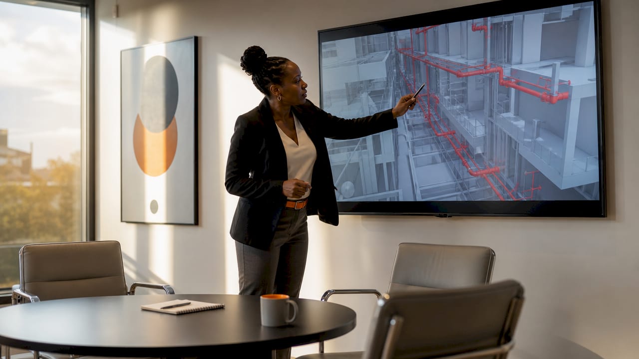
Clash detection is the most direct benefit. Running automated clash checks inside a BIM environment catches pipe routing conflicts, structural interferences, and clearance violations before a single component is cut. Each conflict resolved in the model costs a fraction of what it costs to fix after fabrication.
Level of Development (LOD) is the standard that defines how much fabrication detail a model must contain. LOD 400 models include exact dimensions, connection details, material specifications, and assembly tolerances. A model at this maturity level can feed directly into fabrication without additional drafting. Teams that skip LOD 400 and send under-developed models to the shop create ambiguity that shows up as field errors.
Fixed datum strategies lock all modeled geometry to a universal reference grid. This prevents geometric drift, the gradual accumulation of small coordinate errors that cause factory-built components to miss their installation targets. When every discipline models to the same datum, components from different fabricators fit together on site without shimming or cutting.
- Clash detection: Automated conflict checks catch MEP, structural, and architectural interferences before fabrication begins.
- LOD 400 modeling: Fabrication-critical details, including tolerances and connection specs, are embedded directly in the model.
- Fixed datum alignment: All geometry locks to a universal grid, preventing coordinate drift across disciplines.
- Multidisciplinary synchronization: MEP, structural, and architectural teams work from one shared model, eliminating translation errors between disciplines.
Pro Tip: Set your datum strategy and coordinate system at project kickoff, before any discipline starts modeling. Changing it mid-project forces every team to re-anchor their geometry, which costs more time than the original setup.
What are the measurable benefits of 3D prefabrication integration?
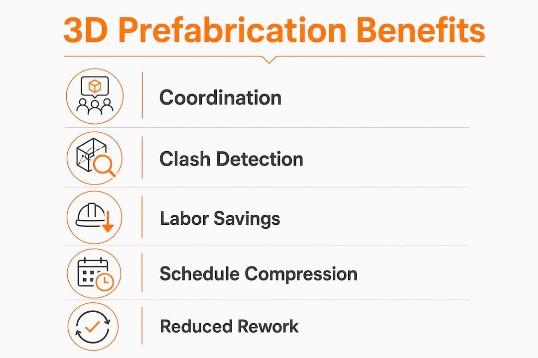
The financial case for BIM-driven prefabrication is specific and well-documented. Project managers who understand the numbers can build a business case that gets executive approval and subcontractor buy-in.
BIM-based heuristic production optimization reduces steel fabrication labor costs by 12.99% while maintaining 99% accuracy in labor-hour estimation. That level of precision means project managers can commit to fabrication schedules with confidence rather than padding estimates to cover uncertainty.
Wall module size alone influences 17.4% of total cost variation in prefabrication projects. That figure shows how early design decisions, made inside the 3D model, have outsized effects on final cost. Getting module dimensions right in the model before fabrication starts is not a design exercise. It is a cost control measure.
| Benefit | Impact |
|---|---|
| Schedule compression | 20% faster project delivery with BIM-driven prefab |
| Labor savings | 30–40% reduction by shifting work to controlled shop environments |
| Rework cost reduction | Rework drops from 5–15% of project costs through early conflict resolution |
| Steel fabrication labor | 12.99% cost reduction through heuristic BIM production optimization |
| Cost variation control | Wall module sizing decisions affect 17.4% of total prefab cost |
Rework is the hidden budget killer on prefabrication projects. When teams resolve conflicts in the model, they eliminate the field conditions that generate rework. The 5–15% rework cost range represents real money on any commercial project. A $50 million project carries up to $7.5 million in potential rework exposure. BIM-driven coordination directly reduces that exposure.
How does 3D modeling support execution planning beyond coordination?
Coordination catches conflicts. Execution planning decides how components move from factory to site and how they install in sequence. Most project teams stop at coordination. The teams that finish on time go further.
Execution planning inside the BIM model means defining spool logic, interface zones, and transportation routes before fabrication begins. Spool logic and interface zone definitions in the model prevent integration failures at assembly seams, which are the most common failure point on prefabricated projects. When the model defines exactly where one spool ends and the next begins, the factory builds to those breaks and the field crew installs without cutting or re-routing.
Standardization of repeated components is another execution planning tool. When the model identifies repeated wall panels, pipe assemblies, or structural connections, the fabricator can batch those components and reduce setup time between runs. Fewer unique components means lower complexity, faster production, and fewer opportunities for error.
3D-driven parallel workflows compress project timelines by enabling fabrication to start during site preparation. Sequential construction waits for site work to finish before fabrication begins. Parallel execution runs both simultaneously. The model makes this possible because it gives the fabricator everything needed to start production before the site is ready to receive components.
- Define spool breaks early. Mark every spool break and interface zone in the model before issuing fabrication drawings. This eliminates field cutting and re-routing.
- Standardize repeated assemblies. Identify repeated components in the model and batch them for production. Standardization cuts fabrication time and reduces error rates.
- Model transportation paths. Map truck routes, crane picks, and staging areas in the model. Conflicts discovered in the model cost nothing. Conflicts discovered on delivery day cost schedule days.
- Sequence installation in the model. Build the installation sequence into the model’s phasing data. The field crew follows the model sequence rather than improvising on site.
Pro Tip: Use the model’s phasing tools to simulate installation sequence before fabrication starts. If a component cannot be installed in the modeled sequence without removing another component first, the sequence is wrong. Fix it in the model, not on site.
What advanced BIM practices drive prefabrication success?
Most project teams use BIM for coordination and stop there. The teams achieving the best cost and schedule outcomes treat the model as a lifecycle data source that spans design, fabrication, and quality control. That shift in how the model is used changes what the model must contain.
Integrating BIM with Work Breakdown Structure (WBS) engines allows automated geometry decomposition and multi-objective optimization of prefab configurations for cost, embodied carbon, and assembly logistics. Instead of manually evaluating configuration options, the WBS engine generates and scores options automatically. Project managers get data-backed decisions rather than engineering judgment calls.
Direct data feeds from the model to CNC fabrication machines eliminate the manual drafting translation step. When the model is at LOD 400 and locked to a fixed datum, the fabrication machine reads geometry directly from the model file. Manual translation introduces errors. Direct feeds do not. This is where prefab-friendly BIM modeling pays its biggest dividend.
| BIM practice | Standard approach | Advanced approach |
|---|---|---|
| Model maturity | LOD 300 coordination model | LOD 400 with fabrication tolerances and connection details |
| Data lifecycle | Design phase only | Design through fabrication and quality control |
| Fabrication interface | Manual drafting from model | Direct CNC data feed from model geometry |
| Configuration optimization | Manual option evaluation | WBS-integrated multi-objective optimization |
| Datum strategy | Discipline-specific origins | Universal fixed datum across all disciplines |
The fragmented data problem limits most BIM implementations. When design data, fabrication tolerances, and quality control parameters live in separate systems, the model cannot support autonomous quality monitoring. Teams that integrate all three into one model gain the ability to check factory output against design intent automatically, without manual inspection at every stage.
For project managers working on prefabricated steel construction, the connection between BIM maturity and fabrication accuracy is especially direct. Steel components have tight tolerances. A model that does not encode those tolerances produces components that require field adjustment, which erases the labor savings that made prefabrication attractive in the first place.
Key Takeaways
BIM-driven prefabrication, built on LOD 400 models with fixed datums and integrated execution planning, is the most reliable method for compressing schedules and cutting labor costs on complex construction projects.
| Point | Details |
|---|---|
| LOD 400 is the minimum for fabrication | Models below LOD 400 lack the tolerance and connection data needed for direct-to-factory use. |
| Execution planning belongs in the model | Define spool breaks, interface zones, and installation sequences inside BIM before fabrication starts. |
| Parallel workflows compress schedules | Fabrication can start during site prep when the model is complete and coordinated early. |
| Early design decisions control cost | Wall module sizing and configuration choices affect up to 17.4% of total prefabrication cost. |
| Fixed datums prevent field failures | Locking all geometry to a universal grid eliminates the coordinate drift that causes assembly errors. |
Why most teams underuse their 3D models
The most common mistake I see on prefabrication projects is treating the 3D model as a presentation tool rather than a manufacturing document. Teams spend time making the model look good for client reviews and then hand a coordination model to the fabricator that lacks the tolerance data, datum alignment, and spool logic the factory actually needs. The fabricator fills the gaps with assumptions. Those assumptions become field problems.
The projects where 3D technology genuinely transforms outcomes are the ones where the project manager treats the model as the contract document for fabrication. Every spool break is defined. Every interface zone is marked. Every component is modeled to the tolerance the factory needs to hit. When the model is that complete, the fabricator does not need to interpret anything. They build exactly what the model says.
The 3D technology uses in construction that deliver the biggest returns are not the flashy ones. They are the disciplined ones. Locking datums, defining WBS structure early, and pushing models to LOD 400 before issuing for fabrication are unglamorous practices. They are also the practices that protect margins and keep schedules intact.
The teams that treat BIM as a manufacturing engine rather than a coordination tool finish faster, spend less on rework, and have fewer safety incidents from field improvisation. That is not a coincidence. It is the direct result of reducing ambiguity before work starts.
, Rendimension
How Rendimension supports prefabrication planning with 3D visualization
Prefabrication projects require more than coordinated models. Stakeholders, clients, and approval bodies need to see and understand what is being built before fabrication begins. Rendimension delivers photorealistic 3D rendering services and immersive walkthroughs that translate complex BIM data into clear visual communication for every audience.
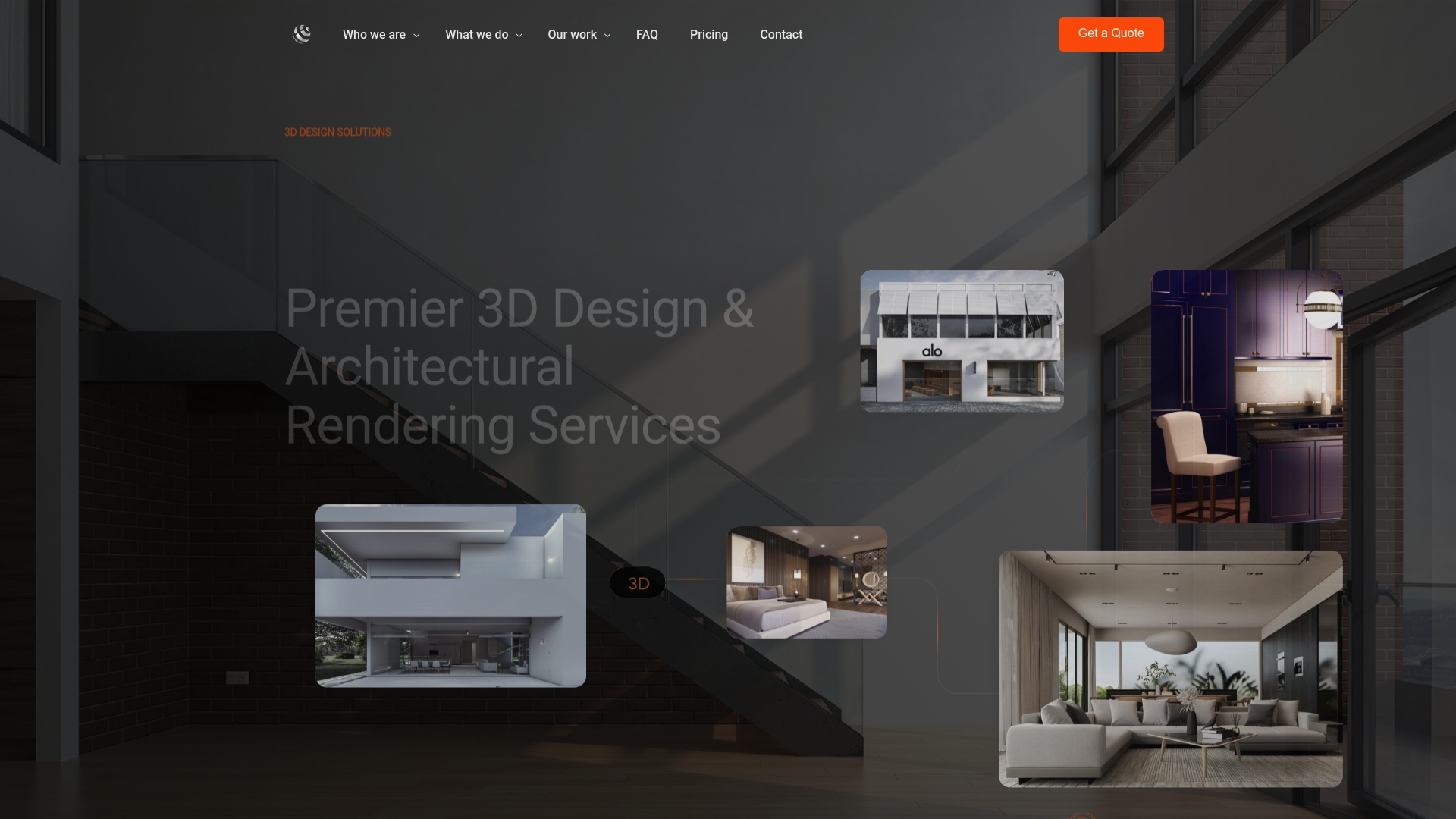
With over 1,000 projects completed globally, Rendimension produces architectural visualizations and 3D walkthrough experiences that accelerate approval workflows and reduce costly late-stage design changes. When stakeholders can see a prefabricated assembly in full detail before a single component is cut, decisions happen faster and with more confidence. Rendimension works alongside project teams from concept through pre-construction, delivering the visual precision that keeps complex prefabrication projects on track.
FAQ
What is the role of 3D in prefabrication planning?
3D modeling in prefabrication planning serves as the manufacturing engine that coordinates design, fabrication, and installation into one data-driven process. BIM-driven prefabrication enables 20% faster schedules and 30–40% labor savings by resolving conflicts and defining assembly logic before factory production begins.
What LOD level is required for prefabrication models?
LOD 400 is the minimum maturity level for prefabrication-ready BIM models. At LOD 400, models contain fabrication tolerances, connection details, and material specifications that feed directly into factory production without additional drafting.
How does 3D modeling reduce rework in construction?
3D modeling reduces rework by catching clashes and design conflicts in the digital model before fabrication starts. Rework accounts for 5–15% of total project costs, and BIM-driven coordination directly reduces that exposure through early conflict resolution.
What is a fixed datum strategy in BIM?
A fixed datum strategy locks all modeled geometry to a universal reference grid shared across every discipline. This prevents coordinate drift and allows factory-built components from different fabricators to fit together on site without field adjustment.
How does 3D technology enable parallel construction workflows?
3D-driven prefabrication allows fabrication to start during site preparation rather than after it completes. This parallel execution compresses project timelines because the coordinated model gives fabricators everything they need to begin production before the site is ready to receive components.
Recommended
- Why 3D Models Are Essential for Builders in 2026
- Top 3D Technology Uses in Construction for Smarter Builds
- What Is 3D Rendering And Its Impact On Architects
Frequently asked questions
What is the role of 3D in prefabrication planning?
3D modeling in prefabrication planning serves as the manufacturing engine that coordinates design, fabrication, and installation into one data-driven process. BIM-driven prefabrication enables 20% faster schedules and 30–40% labor savings by resolving conflicts and defining assembly logic before factory production begins.
What LOD level is required for prefabrication models?
LOD 400 is the minimum maturity level for prefabrication-ready BIM models. At LOD 400, models contain fabrication tolerances, connection details, and material specifications that feed directly into factory production without additional drafting.
How does 3D modeling reduce rework in construction?
3D modeling reduces rework by catching clashes and design conflicts in the digital model before fabrication starts. Rework accounts for 5–15% of total project costs, and BIM-driven coordination directly reduces that exposure through early conflict resolution.
What is a fixed datum strategy in BIM?
A fixed datum strategy locks all modeled geometry to a universal reference grid shared across every discipline. This prevents coordinate drift and allows factory-built components from different fabricators to fit together on site without field adjustment.
How does 3D technology enable parallel construction workflows?
3D-driven prefabrication allows fabrication to start during site preparation rather than after it completes. This parallel execution compresses project timelines because the coordinated model gives fabricators everything they need to begin production before the site is ready to receive components.